Intro
The other day, one of my labmates needed to make a segmentation of Matterport3D. He asked for help, and I got involved in creating the segmentation. However, it turned out to be a real struggle. We were not used to 3D mesh models.
After several weeks, we completed the code to create a semantic segmentation image for Matterport3D.
How to create Matterport3D segmentation images
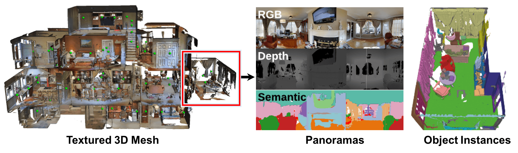
Matterport3D provides access to 3D segmentation but does not give users an easy way to access 2D. Matterport3D data only provides point clouds and meshes labeled by ground truth, and the user must add color directly to the point clouds and meshes to create 2D segmentations.
We, therefore, wrote code using Matterport3DSimulator to place a camera for a given scan_id and viewpoint_id and create a segmentation from the original ply file.
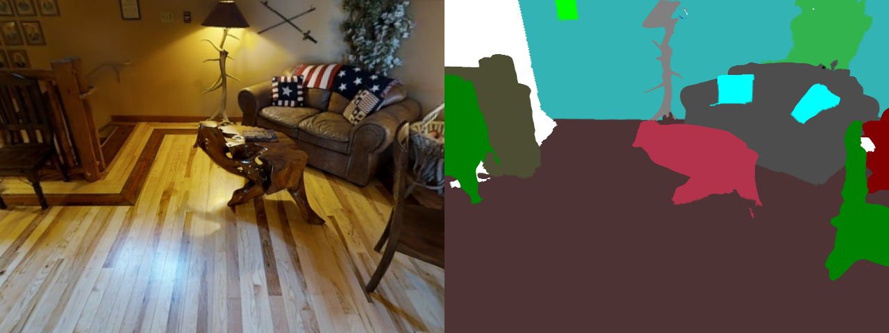
When we run our code, we get the following image. (I concatenated the obtained images and converted to a gif)
Matterport3DSimulator takes a total of 36 pictures: 12 at the top, 12 at the perimeter, and 12 at the bottom. So, we placed the open3D camera using the simulator’s location (x,y,z) and angle (heading, elevation) and take 36 images. Note the difference between the right-hand and left-hand coordinate systems. (This is where we encountered difficulties).